Posts

Showing posts from November, 2016

5G Beam Forming Network

Image
Array Antenna Feed Networks There is various kind of feeding network of an array antenna. Feed network depend on antenna type and geometry. Feed network for microwave applications is a major design concern in terms of complexity and size.
Image
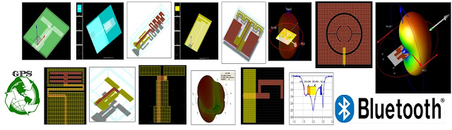
DESIGN OF PLANAR ANTENNAS FOR WIRELESS APPLICATIONS Planar antennas, including microstrip and printed antennas, metal-plate antennas, ceramic chip and dielectric resonator antennas have a low profile hence, these antennas have extensive applications in mobile systems (such as 900/1800 MHz bands), wireless local area networks (WLANs, such as 2.4/5.2/5.8 GHz bands), ultra-wideband (UWB, such as 3.1 ~ 10.6 GHz band) communications. Wireless antennas are used in GSM, WLAN, MAN, CDMA, Wireless Routers, Mobile Handsets, PDA. We can divide these into 3 main categories. Internal dual-/multi-band mobile phone antennas including PIFAs, very-low-profile monopoles, printed loop antennas, printed slot antennas for mobile phones, PDA or smart phones WLAN mobile-unit antennas, including dual-band and/or diversity operations and the antenna mountable above the system, ground plane of the mobile unit UWB antennas for mobile units and access points, including the design techniques for UWB

SIW (Substrate Integrated Waveguide) Patch Antena

SIW technology is essentially a hybrid of microstrip and dielectric-filled waveguide (DFW) technologies. Starting with a PCB substrate, top and bottom metal layers provide two of the waveguide walls. Then, two parallel rows of vias are added, forming the side walls of the waveguide. Figure 1 shows a microwave filter constructed using SIW technology. The SIW technology for passive circuit design has been  implemented for its low cost, compact topology and high performance. There has been increasing interest in implementing SIW technology in active circuits and complete systems, including active integrated antennas.
Image
Higher ORDER MODE ANALYSIS USING FINITE DIFFERENCE Coaxial waveguides and the determination of their cutoff frequencies have been discussed by Marcuvitz . This involves finding zeros of a function that involve products of Bessel functions of 1 st  kind and 2 nd  kind for TM modes and products of derivatives of Bessel functions of 1 st  kind and 2 nd  kind for TE modes. These zeros pertain to a certain order and need a number of iterations to be performed to obtain a set of cutoff wavenumbers. Finite difference methods in the conventional form have been applied t0 a variety of cross sections. However, the same technique involving the formation of rectangular meshes to a circular coaxial waveguide does not seem to be appealing in context with the selection of truncation boundaries and appropriate adjacent node points for the region between the inner and outer conductors. The increase in the number of spurious modes generated and the decrease in accuracy are also detrimental to t

4-Channel Transmit Module with Patch Antenna for 5G Application

Image
Image
MODELING AND SIMULATION OF CHAFF CLOUD Chaff finds are mainly used in electromagnetic countermeasures. A cloud of chaff is an artificial target made up of a bunch of small thin metallized glass fiber or wire. Chaff consists of thin dipole elements cut to resonate at radar frequencies. Chaff Clouds are dispensed in the air through the chaff cartridge on aircrafts . Chaff Cloud masks the real target return signal therefore, the detection of target become more complicated. The reflected signal from the chaff cloud disturbs the opponent’s radar system and creates a false signature in the enemy radar. Because of high RCS signature, after launching a chaff cloud, the incoming missile tends to track on the chaff. The aircraft can then perform a fast, sharp maneuver, deviating from the missile path. Radar Cross Section (RCS) is defined as the area a target would have to occupy to produce the amount of reflected power that is detected back at the radar, and is classified according