DESIGNING WAVEGUIDE FILTERS FOR COMMUNICATION DEVICES
RF/Microwave filters find wide application in communication systems, such as satellite links or wireless base stations. Microwave filters are passive devices employed to select a specific band of the frequency spectrum. Depending on the spectral region that is selected or rejected, they are classified in low-pass filters, high-pass filters, band-pass filters or band-stop filters. Passive devices at the output stage of the communication system must be able to deal with very high power signals. Because of that, waveguide technology is the ideal choice to implement these devices. This work presents the design of a different kind of waveguide-based filter.
Working Principle of Filter?
So, what is magic behind filter? How does it reject signals and pass others? In order to understand this, let us first go through the concept of mismatch. When there is perfect impedance match between the input impedance of system with output load impedance, maximum energy transferred from input to output otherwise there is always some energy loss. A measure of this transmission loss is the reflection coefficient and the related return loss. A frequency dependent mismatch exists in RF/uW devices, due to which signals at those frequencies where the mismatch exists will experience reflection caused by the mismatch. Extreme mismatches are caused by open and short circuits. Filters approach open or short circuit impedances in their stop bands – implying near total reflection. Passive non-resistive filters work by reflection caused by a mismatch condition introduced by the frequency dependent nature of the input impedance. In the bandpass filter (BPF), the resonators and the couplings are arranged in such a way, that the filter is transparent for passband signals. In the stop bands of the filter, the mismatch will cause reflection and thereby attenuation/rejection.
1. 8-Pole Interdigital Bandpass Filter
Interdigital filters are coupled-line structures to implement bandpass filter. The interdigital filter has compact size compared to other coupled line filter hence more popular. Below figure shows one type of 8-pole waveguide based on the center frequency at 1.5 GHz. Each resonator element is a quarter-wavelength long at the mid-band frequency and is short-circuited at one end and open-circuited at the other end. Coupling is achieved by way of the fields fringing between adjacent resonator elements.
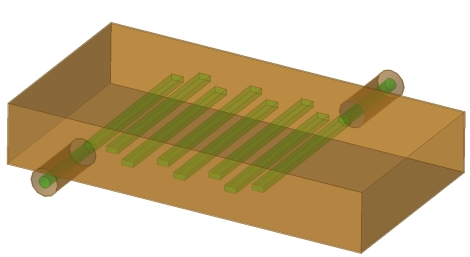
In interdigital filter, the second passband is centered at three times the center frequent y of the first passband, and there is no possibility of spurious responses in between. The rates of cutoff and the strength of the stop bands are enhanced by multiple-order poles of attenuation at dc and at even multiples of the center frequency of the first passband.
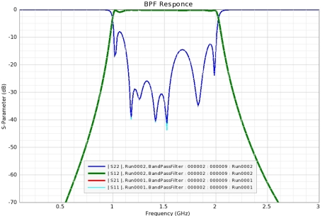
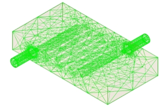 The simulated frequency response of the filter determined using FEM solver is shows the variations of S-parameters with frequency for the L-band interdigital BPF. The unwanted harmonics are suppressed with stop band attenuation better than -14 dB everywhere. FEM mesh and simulated data is are shown in figures.
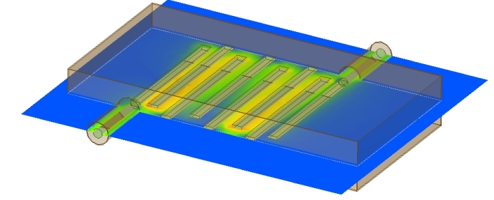
2. Dielectric-filled Co-axial line Filter
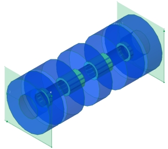 This is dielectric-filled coaxial cable low pass filter that is tuned with five annular rings (irises) that are added to the outer conductor wall in this design. To address the wideband frequency response with a fine frequency resolution, the model is simulated using fullwave 3D electromagnetic solver. The computed S-parameters show a low-pass frequency response with a cutoff frequency around 770 MHz.
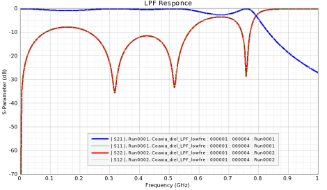 This stepped-impedance low pass filter includes electrically conductive coaxial transmission line, at least one inductive element and at least one capacitive element. The capacitive elements and the inductive elements are disposed in an alternating manner along a length of the transmission line.
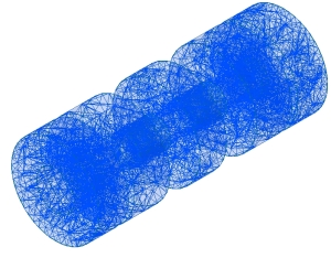
3. Four-Resonator Comb Line Bandpass Filter
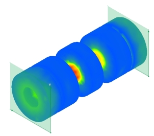
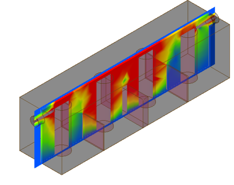
EM simulation is the key design tool for filter design and has reduced experimental 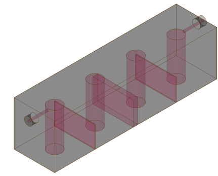 design work for distributed-element and waveguide resonator filters to a minimum or made it completely redundant. The EM simulation involves the calculation of the electromagnetic fields inside the filter structure. 3D EM simulation uses full wave analysis that is what actually exists in nature. 4-resonator combline filter fields at fc and port S-parameter response.
design work for distributed-element and waveguide resonator filters to a minimum or made it completely redundant. The EM simulation involves the calculation of the electromagnetic fields inside the filter structure. 3D EM simulation uses full wave analysis that is what actually exists in nature. 4-resonator combline filter fields at fc and port S-parameter response.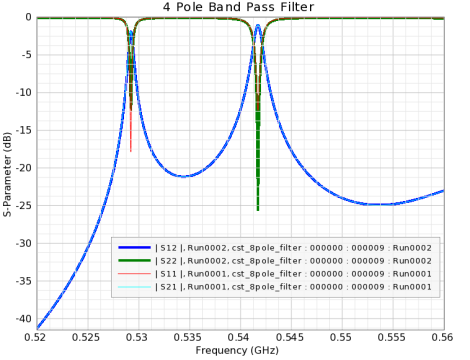
The design and dimensions of the model have been optimized to a point where great performance was significantly shown alongside with good matching around 535 MHz.


Comments
Post a Comment