Dual Channel Rotary Joint

A Rotary Joint (RJ) is a wide spread microwave device that is used to change the direction of microwave propagation between two waveguides by rotating one with respect to another. Rotary joints find many applications in radar and satellite earth stations for functions such as polarization rotation; antenna feed systems and azimuth and elevation motions. Many styles of rotary joints are available for a variety of environmental conditions. Multichannel rotary joints must be carefully designed to achieve low channel loss and small rotational variations of this loss.
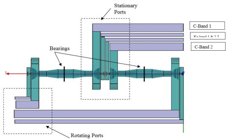
An investigation was first carried out to review the state of the art in the field of multiple-channel rotary joints and to select the types of propagation modes that best satisfied the special system needs. A review of possible design approaches led to the selection of a concentric coaxial line configuration for the main body of the rotary joint, with integral transitions to waveguide at both ends for minimum overall system losses. A sketch of the basic design layout is given in Figure.
Both coaxial line and circular waveguide (CWG) versions are used. To avoid amplitude / phase modulation of the signal transferred through the joint; the axial symmetry of the electromagnetic field is required. To achieve proper field symmetry, the design of the joint is based on using a coaxial microwave line where the TEM mode of the electromagnetic field is propagated. In case a long diameter of axis hole is required, the dimensions of the coaxial line can prove large enough to cause excitement of unwanted waveguide modes. A simple coaxial rotary section operating in the TEM mode is chosen as the basis for the design of this type of joint. Multi number of rotary channels has been increased by the concentric stacking simple coaxial forms. The joint to be described operates in the TEM mode and has low SWR and insertion loss over a wide band of frequencies. It also has no dead spots, showing only negligible variations transmission characteristics with rotation.
The choice of low impedance for this section permitted using a large center conductor, and so made possible the large hole required through the center. When the center conductor becomes this large, however, the increased dimensions introduce the possibility of higher-order circumferential modes existing in the coaxial section. Such a condition would be manifest by phase or amplitude variations of the output signal as the joint is rotated.
The tendency to excite these undesired modes is minimized by careful selection of designing dimensions of coaxial waveguides.A 4-channel C/Ku-band coaxial rotary joint has been designed axially to achieve the desired four-channel operation. To achieve proper field symmetry, the design is based on a coaxial microwave line where the TEM mode of the electromagnetic field is propagated. Multiple rotary channels have been incorporated the concentric stacking of simple coaxial forms. The joint to be described operates in the TEM mode and has low SWR and insertion loss over a wide band of frequencies. It also has no dead spots, showing only negligible variations in impedance and transmission characteristics with rotation. Multisection doorknob type transition is used to obtain broadband performance.
4 CHANNEL ROTARY JOINTS


Comments
Post a Comment