Helical (Helix) Antenna Design
The helix antenna is a travelling wave antenna, which means the current travels along the antenna and the phase varies continuously. Helix antennas (also commonly called helical antennas) invented by John Kraus give a circular polarized wave. Helix antennas are referred to as axial-mode helical antennas. The benefits of this helix antenna are it has a wide bandwidth, is easily constructed, has real input impedance, and can produce circularly polarized fields. There are two mode of circular polarization in helix antenna.
Left handed helix antenna: In left handed helix antenna if you curl left hand fingers around the helix, thumb would point up. The waves emitted from this helix antenna are Left Hand Circularly Polarized.
Right handed helix antenna: In right handed helix antenna if you curl right hand fingers around the helix, thumb would point up. The waves emitted from this helix antenna are Right Hand Circularly Polarized
The minimum number of turns for a helix is between 3 and 5. There are many online tools available to calculate design parameter of helical antenna.
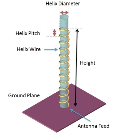
Design parameters for Helical Antenna
- D – Diameter of a turn on the helix antenna.
- C – Circumference of a turn on the helix antenna (C=pi*D).
- S – Vertical separation between turns for helical antenna.
- α – Pitch angle, which controls how far the helix antenna grows in the z-direction per turn
- N – Number of turns on the helix antenna.
- H – Total height of helix antenna, H=NS.
Broad-Band Helix Antenna Design
Below is example of one Helix antenna that work at central frequency 1.35 GHz.
Radius-20 mm
Wire Radius – 2 mm
Number of Turn – 12
Height – 400 mm
Rotation- RHS
Wire Radius – 2 mm
Number of Turn – 12
Height – 400 mm
Rotation- RHS
Helix antennas of at least 3 turns will have close to circular polarization in the +z direction when the circumference C is close to a wavelength.
The helix antenna functions well for pitch angles between 12 and 14 degrees. Typically, the pitch angle is taken as 13 degrees.
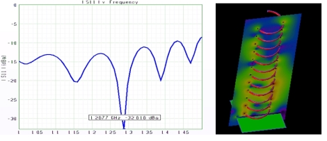
Simulated Result
Antenna is simulated using Finite-Difference Time domain (FDTD) technique. Below is simulated return loss and field plot.
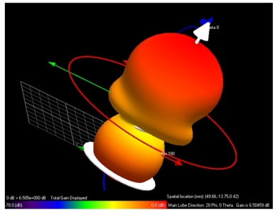 Antenna radiation pattern ( Far Field data plot) is shown below . Antenna Gain is around 15 dB .
There are many other form of Helix antenna like quadrifilar helix antenna.The Quadrifilar Helix Antenna has 4 excitations and each element driven a progressive 90 degrees in phase. Then Bifilar helix is constructed using two volutes with an equal number of turns, and their starting points positioned 180° apart. The ends of the volutes are connected with a shorting wire which adds to the structural integrity of the antenna.


Nice Article.. Thanks for sharing this one post, Keep posting....
ReplyDeleteAntenna Design and Simulations in in India