Signal Integrity Analysis of USB 3.0 Data Bus

USB(Universal Serial Bus) is the most popular connection used to connect a computer to devices such as digital cameras, printers, scanners, and external hard drives. USB is a cross-platform technology that is supported by most of the major operating systems. UART is a computer hardware device that translates data between parallel and serial forms (SerDes). A dual UART (Universal asynchronous receiver/transmitter), or DUART, combines two UARTs into a single chip. The universal asynchronous receiver/transmitter (UART) takes bytes of data and transmits the individual bits in a sequential fashion. At the destination, a second UART re-assembles the bits into complete bytes. Each UART contains a shift register, which is the fundamental method of conversion between serial and parallel forms. Serial transmission of digital information (bits) through a single wire or other medium is less costly than parallel transmission through multiple wires. Below is USB 3.0 onboard interconnect and stack of ground and power nets.

SERDES is a high-speed serial data link used in integrated circuits (ICs) to serialize the parallel data and transfer it at a much faster rate. A typical SERDES architecture looks like a communication set-up with a transmit and a receive side. At transmit side, a PLL generates the fast clock necessary to drive the serializer. A clock and data recovery (CDR) circuit recovers a clock from the transmitted serial data and retimes the data at the receive side. One advantage of using SERDES is reduced clock skew, so data can be sent at the GHz rate. The main disadvantage in SERDES is timing jitter, the deviation of the actual signal transition from the expected transition in time. Timing skew is not a problem in serial interface because in each data lane, there is only one differential signal in each direction, and there is no external clock signal since clocking information is embedded within the serial signal itself.
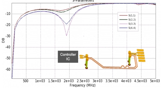 EM simulated data is extracted for USB data group signals and combined with USB connector EM Data. Simulated result of USB connector to USB controller chip is shown here. This data is combined with other channel components for full channel simulation. From this analysis, important factors from a Signal Integrity point of view (e.g., impedance matching, reflection, attenuation, impedance mismatch, propagating delay, crosstalk, and alignment shapes of connectors) are analyzed.
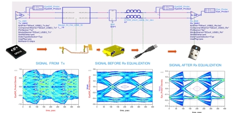
As shown here, without any equalization eye is closed and after applying RX equalization eye is open and meeting USB specification. The idea behind equalization is to use the voltage levels of the other bits to correct the voltage level of the current bit. Due to the inter-symbol interference (ISI) from the frequency dependent loss of the channel, the eye of the received signals is totally closed, and the clock and data cannot be recovered from the severely distorted signals. After the equalizer, the eye of the equalized signals is opened.


Comments
Post a Comment